Perimeter structures
Perimeter structures are designed to capture and retain sediment. These structures on the down slope side of an area prone to erosion can inhibit sediment from leaving the area.
Silt fences
Silt fences are temporary, permeable barriers of geo-textile installed in a trench and supported by star pickets or wooden posts.
A silt fence may be thought of as a leaky dam.
Sediment is treated in two ways:
-
The velocity of run-off is slowed to a point at which it no longer has sufficient energy to hold particles in suspension. This is achieved through a damming of
run-off behind the silt fence. When the run-off no longer has energy to hold particles in suspension, the particles are able to drop out of the water column by gravity. This is how the majority of sediment is removed by a silt fence. -
Some filtration also occurs as run-off passes through the silt fence.
Silt fences should only be used in areas of sheet flow. They're not suitable for use in concentrated flow.
They're most effective in removing coarse particulates from run-off however they have no filtering capacity of fine or dispersive soils.
According to the USA EPA standards test results, the following percentage of fragments will be removed from well installed and maintained silt fences :
|
Soil type |
Percentage removal |
|---|---|
| Total suspended solids | 70% |
| Sand | 80-90% |
| Silt-loam | 50-80% |
| Silt-clay-loam | 0-20% |
Silt fences are an easy and cheap measure to install for large distances, e.g. if an entire, down-slope side of a site must be protected. The use of a silt fence plough can make the job even easier.
Figure 1: Silt fence installation (source: EPA Victoria 2004, Publication 960 p.30)
Silt fence may be reinforced with wire mesh or by placing posts every 1m where there's a risk of being knocked over by run-off flow or wind. Note: the ends must be turned up-slope to allow damming to occur.
Figure 2: Silt fence ends (source: EPA Victoria 2004, Publication 960 p.30)
According to EPA Publication 960, the maximum slope length above the fence should be no greater than:
|
Slope V:H |
Maximum slope length (m) |
|---|---|
| 1:2 | 15 |
| 1:3 | 25 |
| 1:4 | 40 |
| 1:5 | 50 |
| Flatter than 1:5 | 60 |
Silt fences should be regularly inspected to ensure:
-
run-off is not passing under or around the fence (if installed properly this shouldn't be a problem)
-
the silt fence hasn't been knocked over as a result of runoff flows or wind
-
the silt fence hasn't detached from posts
-
no damage has occurred as a result of works on site or due to interference by members of the public
Silt fences require de-silting (removal of collected sediment) when sediment has built up to 1/3 the height of the measure, or when the built up sediment is preventing the silt fence from working effectively.
This generally requires the silt to be shovelled out from behind the fence and deposited in a stabilised area of the site away from run-off flows. It shouldn't be placed up-slope or next to the silt fence where it'll be washed straight back into the silt fence. It also shouldn't be placed down-slope of the silt fence.
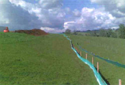
Figure 3: Silt fence (source: Statewide River and Stream Management)
Slowing velocity / trapping measures
Some measures used to slow the velocity of site flows and intercept sediment are described below.
Straw bales
Straw bales are frequently used as a measure to capture sediment in run-off due to their availability.
They should never be used due to their seed content as they will spread weeds.
Sediment is treated in two ways:
-
The velocity of run-off is slowed to a point at which it no longer has sufficient energy to hold particles in suspension. This is achieved through damming of run-off behind the straw bales. When the run-off no longer has energy to hold particles in suspension, the particles are able to drop out of the water column by gravity. his is how the majority of sediment is removed.
-
Some filtration also occurs as run-off passes through the bales. Coarse particulates may be trapped on the outside of the bale and smaller particulates may be trapped within the bale.
They're appropriate to use in areas of sheet flow. They can also be used in concentrated flows if used in conjunction with a silt fence.
They're most effective in removing coarse particulates. They have limited filtering capacity for fine or dispersive soils.
Straw bales alone can be very difficult to get to work effectively as it's very difficult to ensure there are no gaps between the bales. If there are any gaps where run-off is able to pass through, the bales won't work and erosion can actually be exacerbated, as the flow is concentrated through the gap.
It's generally most effective to install silt fence in conjunction with straw bales. In this application the straw bales give the silt fence more structural stability than if silt fence were used alone. The silt fence is placed on the upslope side of the measure, which can prevent damage to the bales in an area of concentrated flow.
Figure 4: Straw bale installation (source: EPA Victoria 2004, Publication 960 p.28)
A line of bales should service a catchment no greater than 0.5ha.
Due to decomposition, bales can require replacement every 3 months.
Straw bales should be regularly inspected to ensure:
-
run-off isn't passing under or around the bales (if installed properly this shouldn't be a problem)
-
bales haven't been knocked over as a result of run-off flows or wind
-
bales haven't begun to degrade
-
bales aren't full of sediment – clogging can prevent run-off from filtering through the bale
-
no damage has occurred as a result of works on site or due to interference by members of the public
Thy require de-silting when sediment has built up to 1/3 the height of the measure or when the built up sediment is preventing the straw bales from working effectively. Bales should also be removed when sediment captured within the bales has clogged the bale, preventing run-off flow through it.
Some individuals often leave straw bales in place when they leave the site, as they believe they will break down. This is the case for the straw bale itself but the posts and twine on the bales won't break down. The posts must be removed and straw bales should be broken up and twine removed.
Coir logs
Coir logs are cylindrical logs comprised of the fibre obtained from the husks of coconuts. They work similarly to a straw bale, however they have greater longevity (1-5 years).
Sediment is treated in two ways:
-
The velocity of run-off is slowed to a point at which it no longer has sufficient energy to hold particles in suspension. This is achieved through ponding of run-off behind the coir log. When the run-off no longer has energy to hold particles in suspension, the particles are able to drop out of the water column by gravity. This is how the majority of sediment is removed.
-
Some filtration also occurs as run-off passes through the coir log. Coarse particulates may be trapped on the outside of the log and smaller particulates may be trapped within the log.
They're predominately used in areas of concentrated flow. Coir logs are also frequently used for creek bed and shoreline stabilisation. They may also be used to protect drainage inlets.
They're most effective in removing coarse particulates. They have limited filtering capacity for fine or dispersive soils.
Dependent on the ground surface it may be necessary to strip an area beneath the log to ensure firm contact with the ground. Coir logs require de-silting when sediment has built up to 1/3 the height of the measure, or when the built up sediment is preventing the coir log from working effectively. Logs will require replacing when they become clogged with trapped sediment.
Rock bunds
Rock bunds consist of a permeable bund constructed from geo-textile encasing rock, and are predominately used in areas of concentrated flow. They're sometimes used as an in-stream measure, however removal of the bund from the stream often resuspends sediment.
Rock bunds are most effective in removing coarse particulates. They have limited filtering capacity for fine or dispersive soils.
Sediment is treated in two ways:
-
As run-off passes over the rocks the velocity of run-off is slowed to a point at which it no longer has sufficient energy to hold particles in suspension. When the run-off no longer has energy to hold particles in suspension, the particles are able to drop out of the water column by gravity.
-
Filtration also occurs as run-off passes through the bund. Coarse particulates may be trapped on the geo-textile and smaller particulates may be trapped within the rock.
Figure 5: Rock bund/groyne construction (source: EPA Victoria 2004, Publication 960 p.34)
They require de-silting when sediment has built up to 1/3 the height of the measure, or when the built up sediment is preventing the bund from working effectively.
De-silting rock bunds may include:
-
removal of sediment from up slope of the structure
-
removal of sediment from the geo-textile (remove, dry out, then beat before replacing)
-
replacement of rock
Synthetic straw bale replacements and logs
Synthetic straw bales and logs consist of a synthetic cover stuffed with synthetic fibres.
Due to their robustness and longevity, these are useful in areas of concentrated flow or where measures are required to remain in place for a long time.
Some synthetic logs have the capability to retain fine particulates.
Sediment is treated in two ways:
-
The velocity of run-off is slowed to a point at which it no longer has sufficient energy to hold particles in suspension. This is achieved through ponding of run-off behind the log. When the run-off no longer has energy to hold particles in suspension, the particles are able to drop out of the water column by gravity.
-
Filtration also occurs as run-off passes through the log. Coarse particulates may be trapped on the outside of the log on the cover. Smaller particulates may be trapped within the fibres inside the log.
Figure 6: Synthetic straw bale installation (source: EPA Victoria 2004, Publication 960 p.34)
Figure 7: Synthetic log installation (source: EPA Victoria 2004, Publication 960 p.34)
Depending on the ground surface it may be necessary to strip an area beneath the log to ensure firm contact with the ground. Synthetic logs require de-silting when:
-
sediment has built up to 1/3 the height of the log
-
the built up sediment is preventing the log from working effectively
-
the log has become clogged and run-off can no longer flow through the log
De-silting synthetic logs consists of:
-
shovelling sediment collected up slope of the logs, away from the area
-
drying out the log and beating it to remove sediment stuck to the outside of the logs and finer sediment contained within the log – when this no longer works and the log is totally clogged, it should be replaced
Rock log-check dams
Check dams are small temporary dams generally installed across a channel to slow the velocity of run-off. They're particularly useful in unstabilised channels which have been seeded, to provide protection until the seed strikes and grass becomes established.
Sediment is treated in two ways:
-
The velocity of run-off is slowed to a point at which it no longer has sufficient energy to hold particles in suspension. This is achieved through damming of run-off behind each dam. When the run-off no longer has energy to hold particles in suspension, the particles are able to drop out of the water column by gravity.
-
Further filtration occurs as run-off passes through the material selected for construction of the dam.
Used in areas of concentrated flow, they're predominately used in drainage channels.
Figure 8: Check dam construction (source: EPA Victoria 2004, Publication 960 p.39)
Sediment basins
A sediment basin is designed so the velocity of run-off is slowed as it ponds in the sediment basin. The velocity is decreased to a state where sediment drops out of the water column by gravity. This system will be necessary on sites with fine or dispersive soil, where other sediment retention devices are not capable of capturing the sediment.
Ideally a qualified engineer should design sediment basins.
Required sediment pond capacity is based on 10m3/ha/1mm of rain, and the total rainfall for a 1 in 2 year 6 hour event. All sedimentation control stems from this.
Rainfall can be determined from the Bureau of Meteorology website based on the coordinates of your site. This will range between 35 and 40 mm for southern Victoria (excluding East Gippsland which has higher rainfall).
Melbourne's 1 in 2 year 6 hour storm has an intensity of 5.9mm/hour, and thus over 6 hours would deliver 35.4mm of rain.
Based on the above and assuming no loss of rainfall you would need to provide a sedimentation pond capacity of 354 m3 per hectare of catchment for the Melbourne area.
Sediment basins must be regularly inspected in order to identify any erosion of the inlets, outlets or basin wall.
Discharge must be controlled and monitored.
The basin will require sediment removed when it has diminished the capacity of the basin by 1/3.
In stream structures
In stream structures should only be used as a last resort or where works adjoin the water body. They shouldn't be relied upon as the sole method of managing erosion and sediment.
Floating silt curtain
Floating silt curtains consist of a curtain of geo-textile supported in the water column by floats and weights. They're an in stream measure only to be used in areas of low flow.
The float width must equal the channel width. The curtain edges must be graduated downwards to match the channel sides.
The curtain must be inspected regularly to ensure it's adequately secure to the floats and weights.
Drainage structure protection
Established drainage inlets should be protected to ensure that sediment can't enter the system. As drainage is constructed on site, any inlets into the system should also be protected. It's important that bypasses into the drainage system are available in case of extreme events in order to prevent sediment laden water bypass protected inlets and enter the drainage system. It also prevents flooding, as inlets are not completely blocked.
RockLogs
Gravel sausages and RockLogsTM or equivalent are permeable sacks (geo-textile, synthetic netting or wire) pre-filled or filled by the user with materials such as coarse sand or aggregate up to 50mm. They're used most commonly to protect kerb inlets.
Sediment is treated in two ways:
-
The velocity of run-off is slowed to a point at which it no longer has sufficient energy to hold particles in suspension. This is achieved through damming of run-off behind the gravel sausage. When the run-off no longer has energy to hold particles in suspension, the particles are able to drop out of the water column by gravity.
-
Some filtration also occurs as run-off passes through the gravel sausage. Coarse particulates may be trapped on the outside of the sausage and smaller particulates may be trapped within the sausage.
Figure 9: RockLog installation (source: EPA Victoria 2004, Publication 960 p.50)
Figure 10: RockLogs (source: Statewide River & Stream Management)
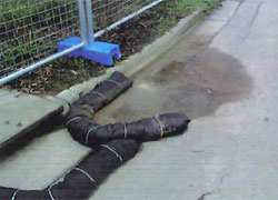
Gravel sausages require de-silting when sediment has built up to 1/3 the height of the measure, when the built up sediment is preventing the log from working effectively, or when the sausage is clogged and run-off can no longer flow through it.
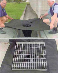
Drain Wardens
A Drain Warden is designed to fit most surface grated catch basins. It traps sediment on silt fence material, which is laid under and held in place by the grate, as run-off flows through it into the stormwater system. An overhang of 100mm of silt fence material (to compensate for the weight of trapped sediment) is left on each side.
This method of inlet protection shouldn't be used in areas where large amounts of flow are anticipated, as there's no overflow into the drainage system. Large amounts of flow will cause run-off to bypass the measure and enter the drainage system further down-slope. Flooding may also occur.
Sediment must be regularly removed to:
-
prevent re-suspension in the next rainfall event
-
prevent OH&S issues associated with lifting pieces of silt fence with large quantities of heavy, trapped sediment
-
prevent clogging
Figure 11: Drain Wardens (source: Prenco)
Silt fence and/or straw bale drop inlet protection
Variations of silt fence and straw bales are commonly used to prevent sediment entering the stormwater system via drop inlets.
Straw bales or straw bales and silt fence should be utilised for inlets with anticipated high flows, as high flows have the ability to knock over silt fence alone. Where maximum filtration is required, a combination of silt fence and straw bales should be used, however maximum damming will also occur.
Sediment is treated in two ways:
-
The velocity of run-off is slowed to a point at which it no longer has sufficient energy to hold particles in suspension. This is achieved through damming of run-off behind the silt fence and/or straw bales. When the run-off no longer has energy to hold particles in suspension, the particles are able to drop out of the water column by gravity.
-
Further filtration occurs as run-off passes through the silt fence and/or straw bale.
Figure 12: Straw bale and silt fence drop inlet filter combination (source: EPA Victoria 2004, Publication 960 p.55)
Silt fence and/or straw bale drop inlet protection structures require de-silting when sediment has built up to 1/3 the height of the measure, or when the built up sediment is preventing it from working effectively.
Where straw bales are used the bales will require replacement approximately every three months as the bales break down and/or become clogged with sediment.
Keeping mud off roads
Minimising site access to vehicles
This is the most effective way of preventing mud being deposited on the road as a result of vehicle movements. Methods may include:
-
restricted access during wet weather conditions
-
minimising on and off site vehicle movements at all times by requiring offsite parking at a paved area
Fencing and signage may be required.
Gravel access points
A gravel access point reduces likelihood of mud being deposited on the road as a result of vehicle movements. As vehicles pass over the gravel track sediment is removed from tyres by friction with the gravel.
In addition, a gravel access point can provide all weather access onto the site.
Figure 13: Gravel access point construction (source: EPA Victoria 2004, Publication 960 p.62)
It may be necessary to install structures around the access point to ensure vehicles don't bypass it.
Built up sediment should be removed from the track. Aggregate should be replenished when necessary.
Rumble grids
Rumble grids remove sediment stuck to the tyres and chassis of vehicles through vibration. Many prefabricated rumble grids are able to open the tread on tyres to increase the amount of sediment removed from them.
Grids may be prefabricated or constructed as follows:
-
using cattle grids, railroad rails or steel bars
-
bar spacing should be S-20cm apart
-
must be designed to cater for the weight of fully loaded vehicles
-
length of grid should be 2 full tyre rotations of your largest vehicle
Some grids are designed to be placed over a pit, while others have spacer bars to create a void under the pit. Material falls between the gaps in the bars into the pit underneath.
Rumble grids may be placed under water to increase their efficiency.
They must be followed by stabilised material to ensure further sediment is not picked up before leaving the site.
Grids must be lifted and sediment collected beneath should be removed periodically.
Grids should be brushed off to remove large pieces of mud or dirt which may not be able to fall through the spaces between bars.
Wheel wash systems
A wheel washing system is a device for cleaning the tyres of trucks when they're leaving a site, to control and eliminate the pollution of public roads. The installation can be made in or above the ground for either temporary or permanent applications. The most common are drive-through systems.
Manual wheel cleaning
Material is physically removed from vehicles using a device such as a broom before the vehicle leaves the site.
This process is time consuming, therefore only relevant for sites with limited vehicle movement on site.
Material removed from vehicles must be placed away from the access track.
Cleaning the road
In the event that sediment is transported onto the road it should be cleaned using a street sweeper, or for small areas by physically sweeping the street.
Where sweeping isn't sufficient and the roads must be washed, kerb inlets must be protected to ensure the sediment is not washed into the drainage system.