Land development reference 5.3.4
This page describes the structural design requirements for drainage systems. It includes details on pipe drains and associated concrete structures.
Approved pipeline systems
The following pipes are approved by us for use in drainage systems:
-
reinforced concrete pipes complying with AS 4058-2007
-
HDPE solid wall
-
profiled high density polyethylene (Black Brute) pipe
Reinforced concrete pipes are always our preference.
HDPE pipes shouldn't be used in Industrial/commercial zoned areas.
Seek our approval for any products other than reinforced concrete pipes.
A special design will be required for any non-standard make-up sections to be included in the proposed drainage system. It may be necessary to obtain specific instructions from us for these sections.
Live loads and concentrated loads
Road traffic loads may be ignored if H > 2.5m (H = depth to pipe obvert). If H < 0.6m, then live loads are assumed to act directly on the pipe.
The following is a list of references with information relating to live loads and concentrated loads:
-
AS 3725-2007 - Loads on Buried Concrete Pipes, Section 6.5, Standards Association of Australia (SAA)
Concrete Pipe Association of Australasia – Loads on reinforced concrete pipes.
Construction loads
A pipeline can be designed without a live load. For example, a pipe won't have a live load if it's laid under an embankment at a depth greater than 2.5m. It'll be necessary however, to check the maximum loading the pipe can sustain from construction equipment at depths of less than 2.5m. This will determine any construction restrictions due to the weight of the equipment and the method of compaction.
Tunnelled and jacked pipes
Tunnelling or pipe jacking is usually necessary for design depths of greater than 6m. Pipe jacking can also be used in locations where existing services or assets make open excavation impractical, e.g. under railway lines or major roads. The type of pipes recommended by us for pipe jacking are specially made to order. They have a butt joint with an external rebate which accommodates a steel locating ring. It's possible to jack short lengths of standard flush joint pipes. They may burst at the joints however, as jacking forces increase.
To calculate the earth load on the proposed pipe, refer to AS 3725-2007 Section 6.3.1.
The pipe jacking bedding factor (F) which applies to jacked or bored pipes should be in the range of 2 to 3.
For more information on pipe jacking, refer to the Technical Note TN24 (J. Daffy) published by the Cement and Concrete Association of Victoria.
Embedment and backfill
Designers should refer to AS 3725 and the Concrete Pipe Association of Australasia Manual for Pipe Bedding and Backfill Requirements.
Concrete Pipe Association of Australasia
All designs require the Pipe Class and Bedding details to be provided on the design plans (on the longitudinal section), i.e. Class 2 FJ RCP/HS2.
It may be more economical to upgrade bedding type rather than to upgrade pipe class.
Example: A 1350mm diameter drain is to be laid in a 2.3m wide trench in a clayey sand. The maximum cover over the pipe is 3.7m. Traffic loads don't need to be considered.
Typical bedding and backfill is H2:
-
using CPAA selection guide
-
pipe class required = Class 3
Alternative bedding of HS2 will provide additional haunch and side support for pipe:
-
pipe class required = Class 2
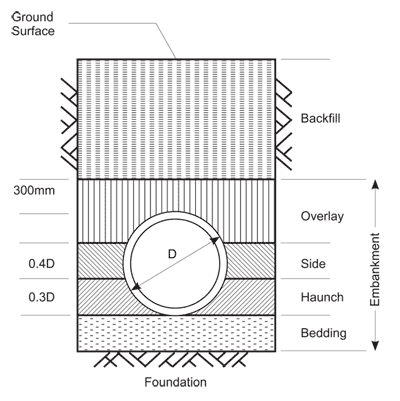
Figure 1 Pipe embedment and zone definitions
Reinforcement cover in corrosive environments
The minimum clear cover to the steel reinforcement for reinforced concrete pipes is listed in AS 4058-2007. It specifies a cover of 10mm for most pipe sizes with flush joints. Additional cover may be required in the design if the proposed drain will be subjected to corrosion by salt water or other aggressive ground water. In this case, the concrete cover over the steel reinforcement must be increased from 10mm to a minimum of 25mm. In an aggressive ground water environment, pipes must be manufactured with sulphate resistant cement in the concrete.
Cement type
The two main types of cement used in drainage works are:
-
type GP General Purpose - this is the normal cement used
-
type SR Sulphate Resisting Cement - this type of cement may be specified for pipes to be laid where aggressive ground waters are expected
Splay pipes and angles
Changes in direction for pipe drains can be achieved at pits or by using splays or bandage joints. The design of splay pipes and angles will be determined by the following criteria:
Splays
-
minimum splay radius (along pipe centreline) = 8D
-
maximum deflection per joint is approximately 5° (depending on manufacturer’s requirements)
-
splay detail tables are required on design plans. Details required include deflection angle, radius and arc length
-
set out details for the splay tangent points are required on the plans
Bandage joints
For how bandage joints can be used, refer to the 7251/08/420 Concrete Make-up joints on curved pipelines drawing
Maximum deflection per joint (degrees) = (18 - D/150) where D is in mm.
Channel lining systems
The use of lined channels should consider construction techniques and aesthetics of the channel. Lining types such as reinforced concrete and rock lining require assessment of the existing soil conditions and stability. Spillways and rock chutes also require special consideration to ensure adoption of the appropriate structural solution for the particular site.
Associated concrete structures
All concrete structures that are to be used in the proposed drainage system must conform to the relevant codes, specifications and Australian Standards.
Table 1: lists the required cover to reinforcement for various typical cast-in-situ reinforced concrete main drainage structures.
| Condition | Min cover (mm) | Sacrificial
concrete (mm) |
Total cover (mm) |
|---|---|---|---|
| 1. External wall face, above ground, exposed to normal weather | 40 | | 40 |
| 2. External wall face, above ground, exposed to sea water and sea spray | 40 | 25 | 65 |
| 3. External wall face, below ground, face poured against forms, normal ground conditions | 40 | | 40 |
| 4. External wall face, below ground, face poured against ground, normal ground water conditions | 65 | | 65 |
| 5. External wall face, below ground, face poured against forms, aggressive ground conditions | 40 | 25 | 65 |
| 6. Internal faces other than invert of rectangular or horseshoe shape drainage structures with normal flow conditions | 40 | | 40 |
| 7. Internal faces above lower quarter points of circular shape drainage structures with normal flow conditions | 40 | | 40 |
| 8. Internal faces other than invert of rectangular, horseshoe or circular shape structures likely to be exposed to seawater | 40 | 25 | 65 |
| 9. Internal face of invert of rectangular, horseshoe and circular shape drainage structures with normal flow conditions | 40 | 10 | 50 |
| 10. Internal face of invert of rectangular, horseshoe and circular shape drainage structures with turbulent and silt-laden flow conditions or exposed to seawater. | 40 | 25 | 65 |
| 11. External face of invert of all drainage structures | 65 | | 65 |
Notes from table 1:
-
Concrete faces exposed to sea water and aggressive ground water must be constructed using an approved sulphate-resistant cement, in addition to the sacrificial concrete used on the exposed faces. An additional protective coating may be specified for the exposed concrete faces of a structure located within a former tip site.
-
The invert of a circular shape drainage structure is considered to be located below the lower quarter points of the structure.
Drain outlets
The outlet velocity of a drain should be considered. If the free outlet velocity is less than 2m/s special outlet conditions are not required.
For pipe velocities greater than 2m/s, the velocity needs to be slowed to ensure the outlet velocity is less than 2m/s. The use of drop structures, energy dissipation structures and large pipes on flat grades can reduce outlet velocities. Consideration of HGL and upstream effects should be included in the design process.
Scour protection measures such as rock beaching may also be required at pipe outlets, particularly where the outlet velocity is greater than 1 m/s, the bed or banks of the channel may be eroded due to the alignment of the outlet, soil types or other factors.
Maintenance access to the outlet structure and safety fencing are other issues needed to be taken into account in designing outlet structures.